Construction details

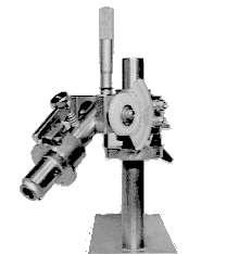
Revision "H"!...In Stainless Steel.

Motors used are DC, either Permanent Magnet or wound field types, having a shaft diameter of at least 1/2" (12.7 mm), and using sealed ball bearings, rated at least 1/5 HP (~150 Watts).
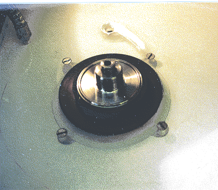
Here is the c-face motor mounted to the underside of the acrylic base. Note the bolt pattern, and the machined splash and dust guard (Made from an old wire spool). The face of the motor was machined dead perpendicular to the shaft, to remove errors caused by the manufacturer's paint. To do so, the motor shaft was mounted to a live center on the lathe's tailstock, and the motor was chucked, after its wires were carefully taped to the body of the motor. This step may NOT be neccesary in most cases. I just did not like the looks of the paint application, and I like to run the lathe, anyway. A "bump" of paint will affect the perpendicularity, just as a shim would.


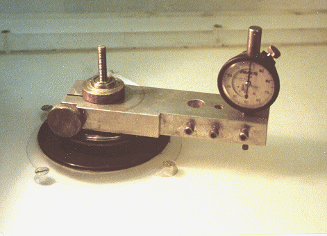
Here is a simple fixture, accurately bored, which mounts on the spindle, and measures wobble relative to the top surface. Since the faceting mast assembly mounts to this surface, and the motor is mounted to the opposite side, this is the datum plane from which measurements are derived, and the plane which is the angular reference for every stone which will ever be cut. The parallelism specs for cast acrylic sheet are very tightly controlled.


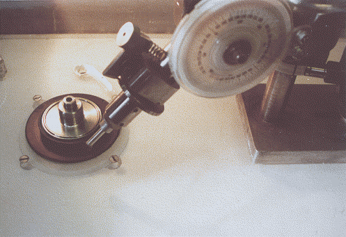
The faceting head assembly, plopped onto the base. It is secured with a single 3/8-24 bolt and clamping nut and washer, so it can slide in and out towards or away from the centerline of the spindle.


Motors used are DC, either Permanent Magnet or wound field types, having a shaft diameter of at least 1/2" (12.7 mm), and using sealed ball bearings, rated at least 1/5 HP (~150 Watts).
Here is the c-face motor mounted to the underside of the acrylic base. Note the bolt pattern, and the machined splash and dust guard (Made from an old wire spool). The face of the motor was machined dead perpendicular to the shaft, to remove errors caused by the manufacturer's paint. To do so, the motor shaft was mounted to a live center on the lathe's tailstock, and the motor was chucked, after its wires were carefully taped to the body of the motor. This step may NOT be neccesary in most cases. I just did not like the looks of the paint application, and I like to run the lathe, anyway. A "bump" of paint will affect the perpendicularity, just as a shim would.


Here is a simple fixture, accurately bored, which mounts on the spindle, and measures wobble relative to the top surface. Since the faceting mast assembly mounts to this surface, and the motor is mounted to the opposite side, this is the datum plane from which measurements are derived, and the plane which is the angular reference for every stone which will ever be cut. The parallelism specs for cast acrylic sheet are very tightly controlled.


The faceting head assembly, plopped onto the base. It is secured with a single 3/8-24 bolt and clamping nut and washer, so it can slide in and out towards or away from the centerline of the spindle.

